Building a Quadruped - Part 1: From a Motor to a Leg
Bench notes: one brushless motor, two controllers on a CAN bus, and a five-bar leg
Table of Contents
This is the first part of a build log about creating a quadruped from scratch. This part covers the first steps, ending with driving a planar five-bar linkage with two motors via CAN bus. The problems along the way are covered as well, e.g. encoder cabling, a second motor axis on the controller that exists in software but not on the board, and figuring out the correct settings for getting the motor spinning under all conditions.
About this series
This is a build log and NOT a tutorial. Everything written here is for one specific setup, and the numbers are derived specifically for it.
The code is available on GitHub: github.com/micha-net/tamnan-robotics
Planned parts:
- From a motor to a moving leg (this part) - PoC for all parts, first single motor actuation, then two motors via CAN and a leg via a five-bar linkage (without abduction)
- Building the full body, by adding abduction to have a full hip, constructing the rest of the body, incl. a new gearbox
- Wiring everything up and building the code for the first movement
- Getting the robot to walk freely, by adding a battery, lidar and a compute unit, then training an AI model, …
3 steps
The goal for this first part gets broken down into 3 steps:
- Single motor actuation. Controlled with a magnetic encoder and a motor control unit, connected via USB.
- Two motors via CAN bus. To work towards the final configuration with 12 joints, a proof of concept with 2 motors controlled via CAN bus was created. The bus setup allows for minimal cabling.
- Two motors driving one leg. The calculation of the kinematics and link lengths, then building the parts via CAD and printing them.
The setup / test bench
As getting parts to my current location took quite a long time due to shipping and customs, I moved for a month to Shenzhen, to source, test and buy all needed parts in bulk. For assembly and testing I booked a desk at Troublemaker Shenzhen, where all needed tools were available.
A full bill of materials is available at the end. Here is a short overview of the most important parts.
| Part | Detail |
|---|---|
| Motor | Eaglepower LA8308 KV90 |
| Controller | ODESC V4.2 - an ODrive v3.6 clone, running ODrive firmware |
| Encoder | AS5047P, 14-bit absolute over SPI (16384 counts/turn) |
| Gearbox | OpenQDD V1 for PoC |
| Power Supply | 40–1,000 VA bench supply |
| Host | Linux, Python 3.9, odrive package 0.6.11, python-can for the bus |
The LA8308 is a 36N40P outrunner with 40 rotor poles and therefore 20 pole pairs. As the ODrive documentation was written for 7-pole-pair motors, a bunch of values had to be re-derived and recalibrated.
The motor is rated for 900 W continuous. For now the motor was run at 24 V, to keep the risk of damage and personal harm low.
The scripts
To get everything running a handful of Python scripts were created along the way, available via the tamnan-robotics repository. The scripts split mainly by transport (USB vs. CAN) for now, rather than by task. The odrive package uses USB only and cannot see the CAN bus at all, while python-can uses the bus and knows nothing about ODrive configuration.
| Script | Purpose |
|---|---|
odrive_motor.py | Shared core to connect, configure, calibrate, arm, sample |
odrive_run.py | Run one motor over USB |
odrive_web.py | Web dashboard to execute and read telemetry |
odrive_can_setup_via_usb.py | Enable CAN on one board and give it a node ID |
odrive_can_check.py | Listen for heartbeats and report what the bus is doing |
odrive_can_run.py | Spin several motors at once via the bus |
leg_kinematics.py | Five-bar geometry, IK/FK, gaits and the cycle check |
leg_run.py | Five-bar leg simulation and execution over CAN |
leg_web.py | Web dashboard to simulate the linkage and get back telemetry |
bench/ | Single-purpose diagnostic tools |
Everything below runs from the repository root:
git clone https://github.com/micha-net/tamnan-robotics.git
cd tamnan-robotics
uv sync          # Python 3.9.6, the odrive package 0.6.11, python-can
Building the one motor setup
The encoder cabling
As a first test, the motor was run via the controller but without encoder feedback. Afterwards the first task was to get the magnetic encoder connected to the setup.
The AS5047P magnetic encoder breakout goes on the ODESC’s SPI header. Both are 6-pin 1.25 mm connectors. Unfortunately the pins did not align.
Encoder (P3):   VCC   GND   CS    SCLK  MISO  MOSI
ODESC (SPI):    GND   MOSI  MISO  SCK   CS    3.3V
A straight cable would put 3.3 V into MOSI and tie VCC to GND. Therefore one end was re-pinned via a breadboard.
The check after recabling is passive. bench/odrive_encoder_raw.py samples the encoder while the shaft is turned by hand.
./bench/odrive_encoder_raw.py --still 5 --duration 20
It reads shadow_count rather than pos_estimate. pos_estimate is the output of the encoder PLL, whose corner is encoder.config.bandwidth, so judging noise from it measures the filter as much as the sensor. Furthermore, a low bandwidth would hide a possible problem.
Controller firmware
The ODESC V4.2 is a v3.6 clone running ODrive firmware and it reports:
Firmware: 0.0.0 Hardware: 3.6.56
ODrive 0.5.0 firmware changed positions from counts to turns, and velocities from counts/s to turns/s. So the task was to find out which config is running. Furthermore, the board mixes features from both generations:
| Present | Absent |
|---|---|
input_vel, SPI_ABS_AMS, turns convention | gpio*_mode, enable_brake_resistor |
motor.config.direction | encoder.config.direction |
pos_estimate and shadow_count track the same shaft, and shadow_count is in counts on every firmware, so their ratio over one hand-turned rotation reveals the convention:
d(pos_estimate) / d(shadow_count) ≈ 1        → counts
d(pos_estimate) / d(shadow_count) ≈ 1 / cpr  → turns
This now runs as part of the hand-rotation check that happens before anything arms, where the operator is turning the shaft to prove SPI works at all. bench/odrive_units_check.py is the same measurement on its own, and takes no arguments:
./bench/odrive_units_check.py
Calibration
First, the encoder offset calibration failed with CPR_POLEPAIRS_MISMATCH, which means the measured counts missed calib_scan_distance × cpr / (2π × pole_pairs) by more than calib_range. bench/odrive_encoder_diagnose.py was created to diagnose the issue:
./bench/odrive_encoder_diagnose.py
The cause was calib_scan_distance. Its default is 16π ≈ 50 electrical radians, which is 1.14 mechanical turns on a 7-pole-pair motor - and only 0.40 turns at 20 pole pairs. Magnet eccentricity produces an angle error that cycles once per mechanical revolution, so it cancels only over whole turns. A partial sweep leaves what remains as a systematic count error of a few percent, which is enough to trip the 2% consistency check with nothing broken at all. The correct value was defined as turns × 2π × pole_pairs and set as calibration timeout. odrive_run.py derives the timeout from calib_scan_distance:
./odrive_run.py \
	--mode velocity \
	--target 1 \
	--duration 10 \
	--recalibrate \
	--encoder-calib-turns 4 \
	--encoder-calib-omega 6 \
	--encoder-bandwidth 400 \
	--current-control-bandwidth 2500 \
	--vel-gain 0.3 \
	--vel-integrator-gain 1.5
The motor is calibrated on the first run via this script, by spinning the motor on its own for twenty seconds. The calibration flag is then set. Recalibration can be triggered via --recalibrate.
Three more significant errors showed up during development:
ENCODER_ERROR_NO_RESPONSE(0x4) means the rotor did not move, not that the encoder did not send signals. The firmware raises it whenshadow_countchanges by ≤ 8 counts across the scan - under 0.2°. So the fault was the magnet mount, not the SPI cable.is_calibratedoutlives reboots. An axis will show it is calibrated on a board where the phases came off / were switched since.- Calibration torque comes from
motor.config.calibration_current, not fromcurrent_lim, and not fromcalibration_lockin.current. Both calibration states apply an open-loop voltage vector, socurrent_limnever clamps them. Turning the wrong one of those three has no effect whatsoever, which is a fine way to spend an hour.
Noise - OVERSPEED without the shaft spinning
With the motor idle and unpowered, vel_estimate read ±2.5 turns/s of pure noise. 4.92 turns/s was peak to peak, which exceeds the 4.8 turns/s overspeed trip that a vel_limit of 4.0 implies. That reading comes from the run script in the mode that connects and streams telemetry without configuring or arming anything:
./odrive_run.py --monitor-only
The cause was encoder.config.bandwidth, which defaults to 1000 rad/s. Setting it to 100 rad/s fixed it. The bandwidth is now written on every run rather than inherited from whatever the last script left in flash, and --encoder-bandwidth overrides it:
./odrive_run.py --encoder-bandwidth 100 --duration 10
Lowering the bandwidth has a floor, because the commutation angle comes from the same PLL.
| Bandwidth | Position error | Electrical error at 20 pole pairs |
|---|---|---|
| 50 rad/s | 0.0080 turns | 58° |
| 100 rad/s | 0.0020 turns | 14° |
| 200 rad/s | 0.0005 turns | 4° |
Velocity gain and integrator gain
A velocity command with gains too weak to break stiction does not move the shaft. The guard that catches it works from total phase current rather than Iq, and it reports numbers rather than asserting a cause:
| Current | Meaning | Response |
|---|---|---|
| Under 15% of the limit | Gains too low to break stiction | Warn once, keep running |
| 15–80% | Ambiguous - something may be holding it | Warn once, keep running |
| Over 80% | The loop has nothing left and the shaft still will not turn | Stop - that current goes into one place with no airflow |
A low d-axis share is not proof that commutation is right. Id and Iq are measured in the frame the controller believes it is in, and the current loop drives Id to zero in that frame whether or not it matches the rotor. A constant offset error therefore reads as 0% while producing only Iq × cos(error) of real torque (nothing at all at 90°). The d-axis share catches an angle turning wrongly but is blind to one that is turning late.
The guard prints the numbers behind every verdict, and while the setpoint is still ramping it judges only saturation. An integrator winding up toward the torque that breaks stiction looks exactly like a stalled shaft, right up until the instant it succeeds.
The integrator is what starts this motor. Proportional gain alone tops out at vel_gain × error, and at 20 pole pairs of cogging torque that is not enough to break free. Both gains are flags, so the difference is one run apart. The following values make the motor turn, but in visible steps. The loop breaks stiction, overshoots, sticks again:
./odrive_run.py \
	--mode velocity \
	--target 1 \
	--duration 10 \
	--encoder-bandwidth 400 \
	--current-control-bandwidth 2500 \
	--vel-gain 0.1 \
	--vel-integrator-gain 0.5
Tripling both, keeping the integrator at roughly 5× the proportional gain, made it smooth:
./odrive_run.py \
	--mode velocity \
	--target 1 \
	--duration 10 \
	--encoder-bandwidth 400 \
	--current-control-bandwidth 2500 \
	--vel-gain 0.3 \
	--vel-integrator-gain 1.5
--current-control-bandwidth is in there for a non-obvious reason. On a 20-pole-pair motor it is a speed limit rather than a response-time setting. Commutation frequency is `pole_pairs × turns/s`, so the firmware's 1000 rad/s default is reached at 8 turns/s, where the current vector lags the rotor by 45° and roughly a third of the torque is gone. Raising it to 2500 buys headroom; the ceiling is about 5027 rad/s, a tenth of the 8 kHz current loop rate, past which the loop amplifies current-sense noise instead of tracking it.
Currently stopping coasts rather than brakes. Commanding zero velocity on a spinning rotor pushes energy back into the bus, and a supply with no brake resistor answers with DC_BUS_OVER_VOLTAGE. Every stop here is a request to IDLE.
One motor, turning
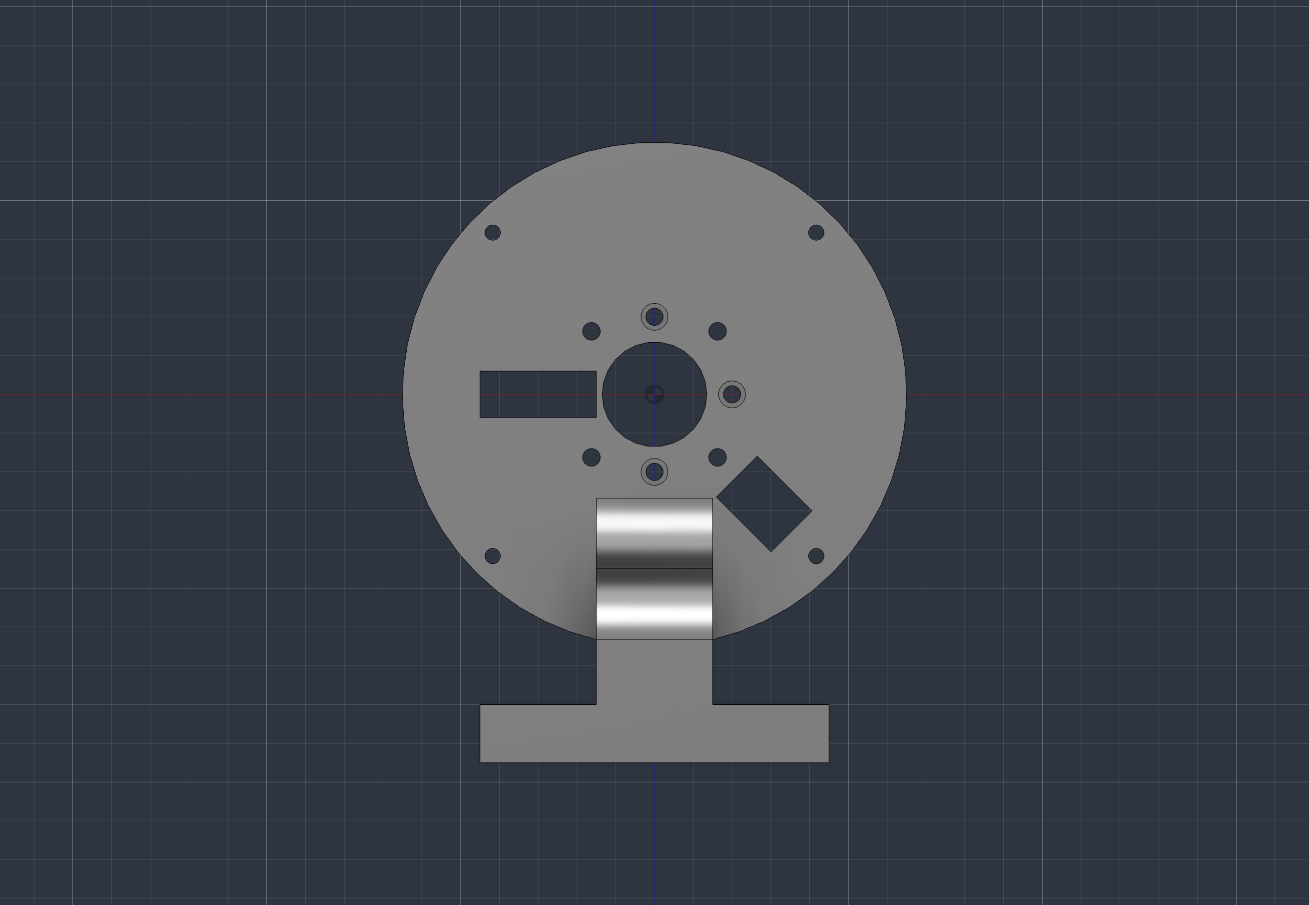
A motor, encoder and controller were connected to a printed stand, to fix it to the desk.
Below are some default values for turns/s for velocity, Nm for torque and turns for position, to get the motor running:
./odrive_run.py                                      # 1 turn/s for 10 s on the encoder
./odrive_run.py --target 5 --duration 30 --csv run.csv
./odrive_run.py --mode torque --target 0.15
./odrive_run.py --web                                # adds http://127.0.0.1:8420
The position mode did need one more gain. ODrive’s position loop is vel_setpoint = pos_gain × pos_error, so at a gain of 20 anything past 0.3 turns of error already saturates a 6 turns/s velocity clamp. The move then travels at the clamp rather than at the speed the gain implies:
./odrive_run.py \
	--mode position \
	--target 0 \
	--duration 30 \
	--encoder-bandwidth 400 \
	--current-control-bandwidth 2500 \
	--vel-gain 0.3 \
	--vel-integrator-gain 0.5 \
	--pos-gain 20
A target of 0 with a duration is a hold rather than a move. The axis arms in position mode, primed with its own measured position, and stays there for thirty seconds. That is useful to feel how stiff a given pos_gain actually is, by pushing the shaft by hand.
--web is a simple dashboard, showing stats and charts for angle, speed, current, power and temperature. In this mode it is read-only; executing odrive_web.py adds a control panel, so the mode, target and the run itself all come from the browser:
./odrive_web.py                            # control panel on 127.0.0.1:8420
./odrive_web.py --monitor-only             # same page, controls disabled

The final result was a running and controllable motor:
Wiring up multiple motors
Each motor control unit provides a USB-C port, to connect to a host. For the 12 joints, 12 MCUs are needed. Individual cabling may work via e.g. a USB hub, but would be messy. Therefore a connection via CAN bus was established.
As the controller configuration cannot be set over the CAN bus, each controller had to be configured via USB first.
Three different scripts have been designed: one script that configures CAN over USB, one that listens to the bus and transmits nothing, and one that commands motion from it.
| Script | Description |
|---|---|
odrive_can_setup_via_usb.py | Enables CAN on one board, sets its node ID, saves and reboots it |
odrive_can_check.py | Listens for heartbeats, reports the bus state |
odrive_can_run.py | Arms several nodes and commands a setpoint |
CAN bus on a breadboard
As a PoC, two boards and a USB–CAN adapter were set up on a breadboard. CAN needs a 120 Ω resistor on both ends. The USB–CAN adapter used has a resistor on board, so only one resistor had to be connected on the breadboard.
Power connections
The power was drawn from a DC bench power supply and distributed to the boards via Y-splitters for + and -.
Each board has five 100 µF capacitors. Two boards on one splitter is ten capacitors charging through a single wire. A current-limited supply will trip the OCP before either board starts up. For two motors with a supply of 6 A and 24 V it was not a problem. Let's see what happens with more controllers on the wire.
ODESC and the second axis
This one cost an afternoon of debugging, and it presented as four unrelated faults.
The ODESC V4.2 has one motor connector, the firmware has two. ODrive’s image for the v3.6 is a dual-axis design, which instantiates axis0 and axis1 by default.
So axis1 is a complete software object on a board that cannot possibly drive it. It has a configuration, a state machine, its own can_node_id, and its own heartbeat. It announces itself on the bus and accepts state requests. It fails only at the point where it needs something physical.
Both axes default to node 0, so setting only axis0 leaves them sharing the same address. Giving the imaginary axis a distinct node ID fixed it:
./odrive_can_setup_via_usb.py --serial <SN> --axis1-node-id 11 --axis1-heartbeat-ms 0
--show reports both axes’ node IDs, heartbeats, states and errors, and warns when the two collide:
./odrive_can_setup_via_usb.py --show # read the configuration, write nothing
The tell was in the first successful bus scan, as one board heartbeated three times as often as the other, with identical configuration. At first this was dismissed as possibly a slightly different firmware version.
Rates, IDs, and a reboot that is not optional
Every node on the bus shares one bit rate. This works, as the nodes have different IDs, but a node clocked at the wrong rate does not just fail to understand the traffic but destroys it. So a single misconfigured board takes the bus down for all of them.
Therefore the following three settings need to be set precisely for each board:
| Setting | If it is missing |
|---|---|
can.config.baud_rate | The peripheral has no rate to clock at |
| axis node id | Must be set and unique - 0 is the unconfigured default |
| axis heartbeat rate ms | 0 disables heartbeats entirely. The board joins the bus, answers a probe, and announces nothing |
After setting the values, each board was rebooted and the values read again, to make sure they were saved. So the setup script saves, reboots, reconnects by serial number rather than by find_any(), reads the values off the rebooted board, and exits non-zero if they did not persist.
Every board ships as node 0, so before they are told apart there is no way to aim a write at one of them: find_any() returns whichever answered first. The setup script therefore refuses to run with more than one board on USB unless --serial names the target. Connect them one at a time:
./odrive_can_setup_via_usb.py --node-id 1     # then the next board as --node-id 2
./odrive_can_check.py --expect 1 2            # both nodes heartbeating?
--expect names the nodes that are expected and exits non-zero for a missing one.
Furthermore, a bus with one live node cannot work even in principle. CAN requires a second node to acknowledge, so a lone board retransmits, fails, and slides toward error-passive rather than heartbeating cleanly. Two powered boards are the minimum setup.
Two Linux details
Two udev rules are needed in a Linux environment to make the board connect. Both live in udev/ and are installed once per machine:
sudo cp udev/91-odrive.rules udev/92-can-up.rules /etc/udev/rules.d/
sudo udevadm control --reload-rules && sudo udevadm trigger
The first is about USB. Without it the ODrive device node comes up root:root 0660, libusb cannot open it, and every connection fails with [UsbInterface] Failed to open USB device: -3 (LIBUSB_ERROR_ACCESS).
The second is about the CAN link, and is not a permissions problem at all. socketcan can be reached over an AF_CAN socket rather than libusb, so no USB rule can affect it. What it fixes is that unplugging a USB–CAN adapter destroys the network interface, and replugging creates a new one: observed as can0 at ifindex 5 coming back as ifindex 6. The up state and the bitrate are gone on every plug. By hand, that is:
sudo ip link set can0 up type can bitrate 250000
The socketcan bitrate is set by the kernel, not by the Python library. The bitrate argument in the library is accepted but ignored.
Both udev rules are part of the Git repository.
Two motors, one bus
odrive_can_run.py arms all nodes in one pass, as a board that arms e.g. two seconds before the other ones is two seconds of one motor pushing a potentially coupled load alone.
./odrive_can_run.py --nodes 1 2 --dry-run     # preflight only, arms nothing
./odrive_can_run.py --nodes 1 2               # 1 turn/s for 5 s, then coast
./odrive_can_run.py --nodes 1 2 --target 2 --duration 10
--dry-run is the preflight part, both nodes set to IDLE with a heartbeat, but no arming. This does not calibrate but will not work without calibration. Calibration needs to be done via USB mode.
A heartbeat carries axis_error and a state. So no current, no temperature, no gains. Therefore the stall guard that worked from phase current over USB has to work from encoder estimates instead, and it can no longer distinguish weak gains from a held shaft or a frozen encoder.
The leg
The first PoC for a leg was two motors, each with a 1:9 gearbox, driving one planar five-bar linkage.
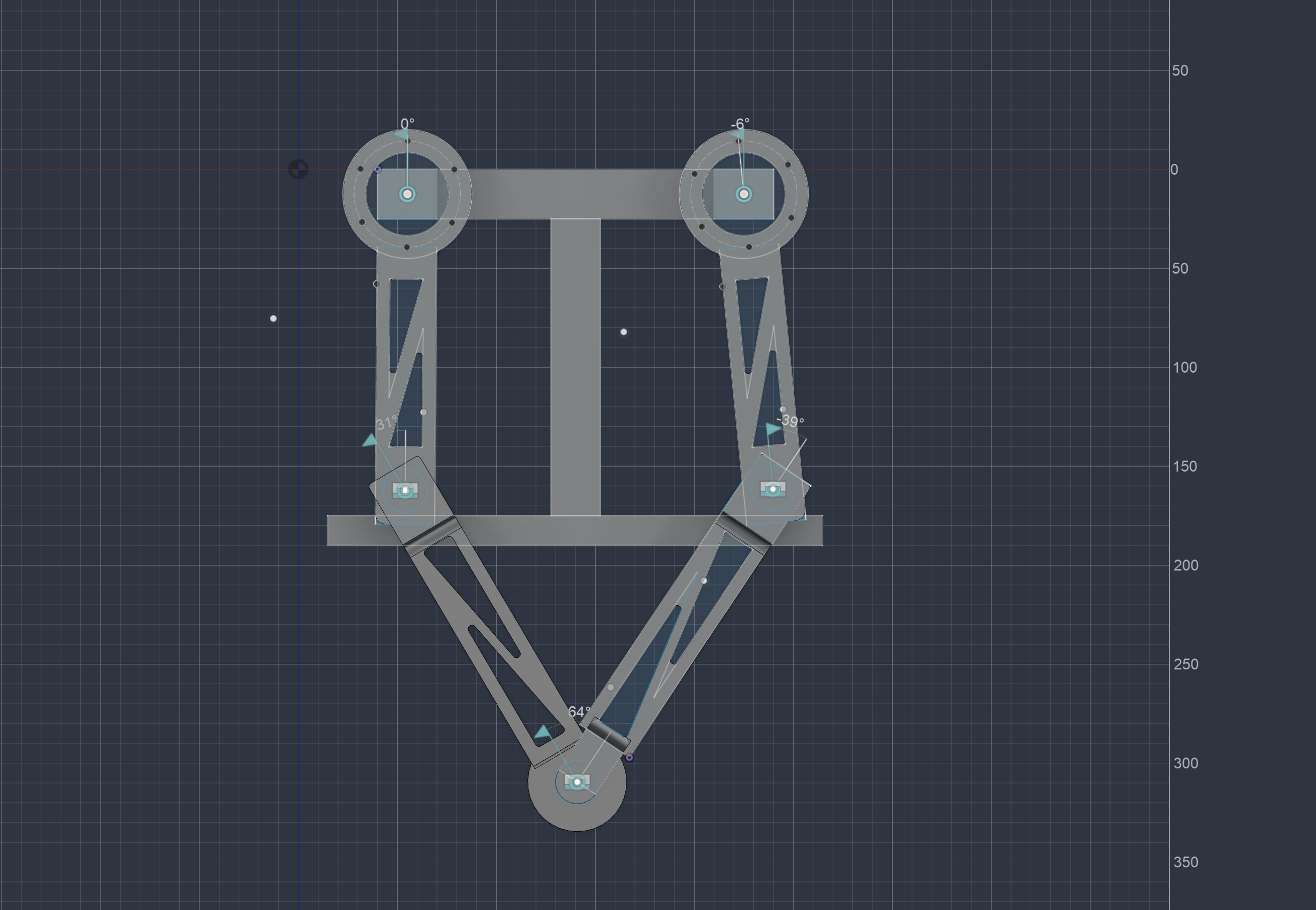
Three scripts have been designed to run the leg: leg_kinematics.py is the geometry with no hardware and no I/O, leg_web.py draws the linkage, and leg_run.py is the one to run.
./leg_run.py                                     # simulate, dashboard on :8421
./leg_run.py --gait trot --stride 120 --check    # cycle check only, no browser
./leg_run.py --live --nodes 1 2 --home-foot 0 -250 --duration 15
Simulation is the default. Nothing is sent to the bus or armed unless --live is given.

Five-bar linkage
Both motors are responsible for a single step of a single leg and sit at the hip. No motor travels with the limb, to keep the leg’s inertia low. This gives the leg the ability to move fast enough to catch e.g. a stumble.
The geometry is two crank pivots hip_spacing apart on a horizontal base, a crank on each, and two lower links meeting at the foot. Currently there is no abduction, so the leg cannot move sideways out of its plane. That would be the third degree of freedom, and will be done in part 2 of this series.
| Component | Measurement |
|---|---|
| Between the hips | 215 mm |
| Cranks | 150/150 mm |
| Lower links | 183 and 169 mm |
That asymmetry of the lower links was a quick fix and will get resolved in further designs. So Geometry defines four lengths and every one of them is a flag, read from a .env file:
./leg_run.py \
	--hip-spacing 215 \
	--upper 150 \
	--lower-left 183 \
	--lower-right 169 \
	--gear-ratio 9 \
	--crank-min -170 --crank-max -10 \
	--min-foot-angle 70
--upper sets both cranks and --upper-left / --upper-right override one side. The crank stops are important to set, as without them a crank can sweep into the chassis. On the test stand nothing physically stops a crank, but just adding -170/-10 prevents a crank from leaving the lower half-plane.
Four ways to close
A five-bar linkage can close four ways for the same pair of crank angles, while a physical mechanism only ever sits in one of them. Forward and inverse kinematics have to agree about which one, or the drawing on screen and the setpoints going to the motors describe different machines.
So the code commits to one assembly mode: knees out and the foot on the clockwise side of the knee-to-knee vector. Then the code checks it on every single pose, by running each IK result back through FK and reporting the distance between them. It reads 1e-13 mm when the conventions agree and tens of millimeters when they do not. A pose that has drifted onto another branch gets reported rather than drawn.
That round trip is also what leg_kinematics.py runs as its own test, over the whole workspace, with no hardware and no bus involved:
./leg_kinematics.py --self-test
Checks
Before a live run arms, the whole gait cycle (361 points) is walked. --check runs only that:
./leg_run.py --gait trot --stride 120 --clearance 40 --period 1.2 --check
| Finding | Why it is a refusal |
|---|---|
| A point outside the linkage | With the distance it is short by, at the phase it happens |
| The lower links within 5.7° of straight | The Jacobian is singular there: the foot cannot be driven along the line through the knees at any torque |
| A chain past 99.5% of full extension | The same singularity, seen from one side |
| Knees crossing | Whatever the maths says, the links occupy the same space |
| The lower links closing inside the minimum foot angle | The same collision at the other end of the linkage |
| A crank past its configured stop | The stop is where the chassis begins; the simulator has no other way of knowing that |
| IK and FK disagreeing | The path leaves the assembly mode, and a real linkage cannot change branch without passing through a singularity |
| Peak motor speed past 60% of no-load | 36 turns/s no-load at 24 V and KV 90; past that, back-EMF leaves too little voltage for current and the loop stops tracking |
The straightness metric catches the links going straight, resulting in a singularity. The foot-angle floor catches them shutting on each other like scissors, which the straightness metric reads as its safest possible value right up to the collision. Both default to unconfigured and say so in the report, rather than implying the leg is guarded when it is not.
Currently there are no dynamics calculated in the simulation, so no mass, friction, backlash, gearbox loss or current loop. Again, this will be added in a later part.
Starting point and execution
An ODrive position estimate counts turns from wherever the encoder happened to be zeroed. That has no relation to where a crank is actually pointing. Currently there is no homing, so during execution the human confirms that the foot is at this coordinate right now - that is what --home-foot X Y is:
./leg_run.py \
	--live \
	--nodes 1 2 \
	--home-foot 0 -250 \
	--gait trot --stride 80 --period 1.2 \
	--duration 15 \
	--pos-gain 20 \
	--current-limit 5
The run then proves the declaration rather than trusting it:
- The cycle check runs. Any error and nothing is armed.
- Bus preflight: both nodes IDLE, clean, heartbeating.
- The declared pose becomes a motor-turns offset per axis.
- Both axes arm in position mode, each primed with its own measured position first. A position loop closed around the
0.0left in the setpoint field is a dash to encoder zero at the velocity limit. - The leg holds still, and a browser page draws the pose this run believes it is in. Does the drawing match the real leg? If not, the mapping is wrong and nothing has moved.
- A 20 mm nudge of the foot in
+x, drawn before it is commanded. Did the foot go the same way? If not, a motor direction is inverted relative to the model. - Only then a slow move to the start of the path, and only then the gait.
Steps 5 and 6 are two questions no sensor on this bench can answer, and they are the entire reason a visual dashboard exists rather than a log file. A failed step 6 is a motor direction inverted relative to the model, and the fix is to stop and re-run with --invert-left or --invert-right. --skip-visual-check turns both off; it is for a mapping already proven this session, not for a first run.
--nodes takes the two node IDs in the order LEFT RIGHT, and gets them wrong silently if they are swapped - which is another thing step 6 catches.
Both axes are also written in one pass with nothing between them. A five-bar with one crank a frame ahead of the other is a linkage being asked for a pose neither motor was told about.
Conclusion for part 1
Part one was acquiring the right parts and showing a PoC of all parts assembled. To add abduction and the rest of the body should be “just” a scaling problem now.
Part 2 will show the construction of the full body, including abduction as the third degree of freedom.
APPENDIX - Bill of materials
The list below contains all parts needed for the full four-legged robot, not just for this part of the series - e.g. twelve motors and twelve controllers, three actuators per leg. The third one per leg is the abduction axis that Part 2 is about.
Some minor additional parts were sourced, to make sure everything is available in case of deviation from the plan.
| Item | Qty | ¥ RMB | € EUR |
|---|---|---|---|
| Eaglepower 8308 KV90 brushless motor | 12 | 4,500.00 | 572.13 |
| ODESC V4.2 brushless servo controller (ODrive 3.6 compatible) | 12 | 3,156.00 | 401.25 |
| Magnetic encoders + magnets (AS5047P) | - | 433.20 | 55.08 |
| Thin-section deep groove ball bearings, 65 mm bore | 12 | 205.20 | 26.09 |
| 6001RS deep groove ball bearings, 12 × 28 × 8 mm | 10 | 163.99 | 20.85 |
| Knurled brass thread inserts, 370 pcs | 1 | 154.06 | 19.59 |
| Brass heat-set inserts, M2–M6, knurled | 30 | 90.81 | 11.55 |
| PLA+ filament, 1.75 mm, 1 kg | 2 | 70.20 | 8.93 |
| USB–CAN module | 2 | 65.96 | 8.39 |
| JST-SYP/PH 2.0 mm connector kit, 2–5 pin | 1 | 49.00 | 6.23 |
| USB–CAN debugger / “PCAN analyzer”, 1 Mbit/s | 2 | 45.50 | 5.79 |
| 608ZZ deep groove ball bearings, 8 × 22 × 7 mm | 10 | 40.00 | 5.09 |
| GH1.25 mm crimped cable + DuPont shell assortment | 1 | 39.50 | 5.02 |
| Screws and nuts, mixed | - | 39.50 | 5.02 |
| Breadboard, 830 tie points | 1 | 39.36 | 5.00 |
| Push-in wire connector terminals, 1-in multi-out | 10 | 36.88 | 4.69 |
| Brass heat-set inserts, M1–M8, knurled | 50 | 32.50 | 4.13 |
| Push-in wire connector terminals, 1-in multi-out | 10 | 29.47 | 3.75 |
| Metal film resistor kit, 600 pcs, 1/4 W | 1 | 27.58 | 3.51 |
| M3 hex brass standoffs, single-head | 80 | 10.73 | 1.36 |
| Screw, nut and washer set, M3–M6 | 1 | 9.09 | 1.16 |
| Mini self-adhesive breadboard | 5 | 4.55 | 0.58 |
| XH2.54 2-pin wire-to-board connector, 24 AWG | 1 | 0.12 | 0.02 |
| Total | 9,243.20 | 1,175.21 |
Quantities are as recorded on the sheet (a few of the kit lines are counted in packs rather than in pieces). The live version, with the original Taobao marketplace listings, is available here: Bill of materials (Google Sheets).
Motors and controllers are 83% of the entire robot - €973 of €1,175.